What Can We Learn From Vacuum Tube Electronics?
A Brief Introduction
I realize many technicians reading this email may have never seen a vacuum tube. You may be surprised to learn that there was a time in the history of electronics when there was no such thing as a transistor, integrated circuit, computer or iPhone. The first transistor was not developed till 1947. Transistors developed and began to appear in electronic equipment in 1953. The first all transistor car radio experiment was introduced in 1955, produced by Philco for Chrysler Imperials. The world began to change dramatically.
In the beginning days of electronic equipment in the early 1900's all electronic equipment was built with vacuum tubes up until the 1960's. Gradually transistors began to take over in electronic circuits and vacuum tubes faded from view leaving behind two very important electrical terms we still use today. These two electrical terms are the reason for this article.
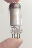 This is what a vacuum tubes looks like in case you have never seen one. The vacuum tube is being held between two fingers to snap this picture. The tube image is almost life-size for this 6EB6 type vacuum tube. Notice the tube's external pins sticking out from the bottom. You can see wires through the glass of the vacuum tube's glass envelope that connect the elements inside the vacuum tube to the external pins. The vacuum tube is inserted into a "tube socket" wired to integrate the tube into the circuit. Each vacuum tube does the job of one single transistor.
A vacuum tube requires enormous electrical energy to operate compared to a transistor which takes very little energy to do the same job. Very heavy power supplies had to be built to operate vacuum tube circuits. The heavy-duty power supplies used vacuum tubes to create the voltages necessary for vacuum tube operation. They generated a tremendous amount of heat to add to the heat generated by the many vacuum tubes in an electronic chassis. Often times cooling fans were required to dissipate the heat. I remember growing up with our first vacuum tube television set (1949) that got so hot a newspaper left on top of the TV cabinet could catch fire. In other words, electronic circuits with vacuum tubes got really hot. Ah, but I digress thinking about the old days watching TV with vacuum tubes and no air conditioning.
How can I describe the changes in the world of electronics since vacuum tubes were replaced by transistors and transistors were replaced by integrated circuits? Let me phrase it this way. It is like going from flying a propeller powered light airplane to "warp drive in outer space" to borrow a term from Star Trek.
In order for a vacuum tube to function in an electronic circuit, two separate power supplies are required. A low voltage power supply in the range of 1.5V - 12V is needed for vacuum tube filaments and is called the "A" Power Supply. A high-voltage power supply in the range of 100V - 600V is required for Plate voltage and is called the "B" Power Supply. As vacuum tube technology improved over the years vacuum tubes were developed that could operate at lower voltages.
This is the schematic diagram of a vacuum tube circuit. The vacuum tube is drawn as a circle and the tube elements are drawn inside the circle. Around the circle are pin numbers connecting the tube elements to external circuitry.
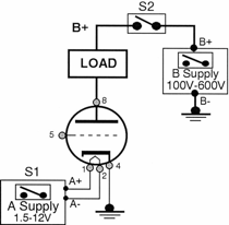
Figure 1
Pins 1 and 2 connect to the tube's element called the Filament wire. This acts the same as a filament wire inside a lamp bulb. The filament is connected to the low-voltage "A" supply. Notice the "A" supply has a (+) terminal and a (-) terminal.
Pin 4 connects to the element called the Cathode which is grounded to have a source for electrons.
Pin 8 connects to the element called the Plate. The Plate connects to the high voltage supply called the "B" supply. Notice the "B" supply also has a (+) terminal and a (-) terminal.
The load is inserted between the Plate (Pin 8) and the positive terminal of the high-voltage "B" supply. The voltage appearing at the (+) terminal of the high voltage supply came to be called "B+" and the voltage could vary from 100 VDC to 600 VDC depending on the circuit. The high positive voltage draws electron current through the tube and through the load to get the load into operation.
Pin 5 is the Control Grid which is used to control the amount of electrons that pass through the vacuum tube. For purposes of this discussion, let's just say the voltage placed on the Control Grid in this situation allows maximum electron current to flow through the vacuum tube when B+ is applied to the Plate.
If you drive an electron current through an incandescent lamp's filament it glows white hot. You can see the filament glowing (the light produced) and feel the heat being radiated. A similar thing happens in a vacuum tube when the "A" supply is turned ON. Electron flow from the "A" supply passes through the Filament causing it to glow red hot which heats up the Cathode shown in Figure 2.
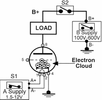
Figure 2
The electron current through the tube's Filament creates heat and an "electron cloud" is created around the Cathode as the Cathode heats up. Electrons literally boil off the surface of the heated Cathode and hover there. Electron current through the Filament does not become part of the electron cloud. Electron current in the Filament is used solely to heat up the Cathode to create the electron cloud. (Vacuum tube advances eventually combined the filament and the cathode into one tube element.)
At this point there is no electron current flowing through the vacuum tube and through the load. There is just the electron cloud hovering around the Cathode. But the vacuum tube is hot and the Filament is glowing red hot. To get electrons to flow through the vacuum tube and through the load so the load can begin to operate, a high positive voltage, B+, is applied to the Plate by closing switch S2 as shown in Figure 3.
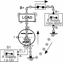
Figure 3
The high positive voltage on the Plate, "B+," attracts electrons from the electron cloud which flow into the Plate, through the load and to the positive terminal of the high-voltage "B" supply or "B+." (Sound familiar? The electrical term, B+, started with vacuum tubes and is still used today to identify the highest positive voltage in a circuit. In a vehicle, the highest positive voltage is called generator charging voltage. We identify this positive voltage as B+. )
Remember the Cathode is grounded as is the negative terminal of the "B" high-voltage source. The "B-" (say B- minus) terminal continues to supply electrons to ground which channel through ground to find their way up the Cathode to replenish electrons leaving the electron cloud. As electrons are removed from the electron cloud and flow to the plate, electrons are replaced in the cloud as long as the Cathode remains red hot and B+ is applied to the Plate.
To shut off the vacuum tube circuit both the high-voltage and low-voltage power supplies are turned OFF. It may take several minutes for the vacuum tube to cool down enough to be touched by human hands. It was common practice to remove vacuum tubes from electronic equipment and plug them into a tube tester that checked the tube's operation. Tubes that failed the test were replaced.
Electron Theory
You could never explain how a vacuum tube circuit worked using positive current flow. What happens in a vacuum tube, as we have just seen, is electron current flow (B-) to (B+). That is the only possible explanation for how vacuum tubes operate. Electron flow is the same in all vehicle circuits as we have been studying through this series. Electrons flow from the (-) negative terminal to the (+) positive terminal.
There Are Two Electrical Principles To Take Away From Vacuum Tube Theory!
- The term "B+"
You now understand where the term "B+" comes from. It refers to the highest positive voltage in a circuit and continues to be used in solid-state circuit explanations today. In vehicles, the highest positive voltage is the charging voltage we refer to as B+. - Direction of Electron Current
Electrons have always flowed from the (-) negative terminal of the voltage source (B-) as they travel through the circuit and return to the (+) positive terminal (B+) of the same voltage source. Vacuum tube theory proves it.
Study more advanced electronics theory, operation and troubleshooting of solid-state components, such as, diodes, transistors and integrated circuits in Lessons 42 through Lesson 60.