Ground Electron Current Part 2 of 9 Parts
The first electron current that occurs in a vehicle electrical circuit, when the engine is not running, is when battery cables are connected to a charged battery. Any circuit connected to “hot at all times” has battery voltage available to it “all the time” as shown by Fuse F2 at the top of the diagram. The Lamp Circuit #2 (on the right) can operate if switch S3 is CLOSED because battery voltage is available through Fuse F2. Lamp Circuit #2 does not depend on the ignition switch position. However, Lamp Circuit #1 cannot operate until the ignition switch is CLOSED and switch S2 is CLOSED.
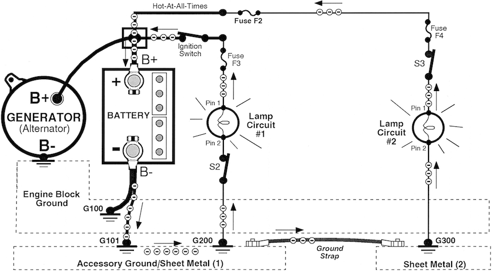
Fig 2 Battery Electron Current Path
We are using two simple lamp circuits to illustrate the path of battery electron flow through the vehicle. It doesn’t matter if the lamps were replaced by complex circuitry. Later on in this series, we will add additional complex circuits to the sheet metal. The path of electron flow would not be any different so why not use two simple circuits to explain principles of electron flow? I’ve often found it easy to explain complex electrical or electronic circuit principles using simple circuits. Electron flow doesn’t care how simple or how complex the circuit. It will flow through the circuit when the path is complete.
To place the vehicle in operation the ignition switch must be CLOSED as shown above in Figure 2. Battery voltage is now available to provide electron current to any circuit that is operating, which means any circuit that is turned ON. Electron current flows from the negative battery terminal through the circuit to return to the positive battery terminal.
Electrons leave the battery negative terminal and flow down the accessory ground cable to G101. Electrons then “channel” (flow) through a direct path in the sheet metal. Notice we have accessory ground/sheet metal (1) connected to sheet metal (2) by a ground strap. This supplies electrons from sheet metal (1) to sheet metal (2). Any circuit grounded to either sheet metal (1) or (2) will have access to electron flow provided the circuit is turned ON.
Electrons enter Lamp circuit #1 at G200 and travel up through the circuit when S2 is CLOSED turning the lamp ON. Electrons flow through the lamp causing it to operate, continue through the fuse, through the closed ignition switch to the battery positive terminal which completes the circuit for Lamp Circuit #1. Every electron that enters Pin 2 of the lamp (the ground side of the lamp circuit) must exit at Pin 1 of the lamp (the voltage side of the lamp circuit). Electrons continue flowing through the Lamp Circuit #1 through fuse F3 and return to the battery positive terminal.
Electrons leave sheet metal (1) and flow through the ground strap to supply electrons to sheet metal (2). If switch S3 is CLOSED a path for current exists through Lamp Circuit #2. Electrons enter G300 and flow up the ground wire, through lamp circuit #2 turning the lamp ON. Electrons continue flowing through the closed contacts of switch S3, fuse F4, fuse F2 and return to the battery positive terminal.
Remember this very important fact of electron current we have just described. If an electron leaves the negative terminal of the voltage source it must return to the positive terminal of the same voltage source. If the electron cannot do that it will never leave the negative terminal in the first place.
If switch S2 is switched OFF or “OPEN,” electron current through Lamp Circuit #1 will stop but Lamp Circuit #2 will continue to operate. The opposite is true. If S3 i is switched “OFF” or “OPEN,” electron current through lamp circuit #2 will stop but lamp circuit #1 will continue to operate.
Notice the engine block battery cable connects to G100. We did not mention any electron current flowing down the engine ground to the engine block. If any circuit were grounded to the engine block there would be some battery electron current flowing down the engine ground into the engine block. The only circuit we show connected to the engine block in this diagram is the generator. If this generator has an internal initializing circuit that is used to start the generator producing electricity as it begins turning, there would be a small electron current flowing through the engine ground. If the generator does not use an internal initializing circuit there would be no current through the engine ground at this time.
From this simple illustration, we can see why the ground circuit is so important to electron flow through any circuit that is properly grounded (connected to sheet metal) and turned ON. If ground G200 or ground G300 is corroded, it will impair the electron flow through that circuit. This understanding will form the basis for explaining how to measure electron flow through the ground circuit and how to best troubleshoot ground circuits by voltage measurement in future articles.
Answering Ground Circuit Questions
I received the following email from a teacher in heavy duty technician training. I quote his email below in full. I have inserted blue markers to indicate a statement and two individual questions that deserve an answer. Some of you may have similar questions.
Hi Vince:
I have been following and enjoying your emails for several years and use your theories in my Heavy equipment technician classes.
(Statement ) I understand the two camps of conventional flow and electron flow.
(Q.1) In the first installment of this series you mentioned that Bat+ was the "supply" and in this second one you mention the "battery voltage is available through fuse #2" Several of my former students regularly contact me as they also follow your emails. Some of them have been asking about why this email series seems to indicate that Bat + (+BATT ed.) is the voltage supply but the electrons are flowing from the negative post to the positive post.
(Q.2) Also in an electron flow circuit, why are the fuses after the load if they are intended to protect the load from excess current? In these diagrams the excess current would first have to travel through the load before the fuse would be able to do it's job.
I wanted to forward these questions and await your reply. Thanks again for all of the email content it is always helpful and sometimes stirs up some good conversation.
Dave F.
Dave's Statement: I understand the two camps of conventional flow and electron flow.
My Comment
One version of electrical current is correct and the other is incorrect. They both cannot be correct. The scientific community assures us that electrical current is the movement of negatively charged particles we call electrons. Electrons leave the negative terminal of the voltage source, travel through the circuit and return to the positive terminal of the same voltage source. If an electron leaves the negative terminal and enters the circuit, at the same instant in time, an electron must leave the circuit and enter the positive terminal to maintain the same number of electrons in the circuit at all times.
Think of the circuit as if it were a large diameter pipe several feet long and filled with ping-pong balls, all resting quietly in place. You have an extra ping-pong ball leftover and try to push it into the pipe to get rid of it. What happens at the other end of the pipe? All ping-pong balls become agitated and move a little so a ping-pong ball can pop out the other end to make room for the new one you just pushed into the pipe. The pipe always contains the same number of ping-pong balls. Think of these ping-pong balls as electrons in the circuit. If an electron enters (is pushed into) the circuit at the negative terminal ("ground side") all electrons in the circuit path become agitated and move so an electron leaves (is pulled out of) the circuit and enters the positive terminal ("voltage side"). The circuit always contains the same number of electrons.
Electron flow is measured in units called "amps" and is measured with an ammeter or a current clamp. Measuring electron flow in amps has nothing to do with measuring voltage with a voltmeter. They are two separate and distinct measurements taken in a circuit to evaluate circuit conditions.
(Q.1) In the first installment of this series you mentioned that Bat+ was the "supply" and in this second one you mention the "battery voltage is available through fuse #2" Several of my former students regularly contact me as they also follow your emails. Some of them have been asking about why this email series seems to indicate that Bat + (+BATT ed.) is the voltage supply but the electrons are flowing from the negative post to the positive post.
Figure 2 Battery Electron Current
Answer to Q.1
Don't confuse measuring voltage (in volts) and measuring electron current (in amps). We usually measure the voltage first because we need to know if we have enough voltage to power the circuit. We turn the circuit ON and then we measure the electron current if necessary to determine if enough electron current is flowing or not. This is the beginning principles of troubleshooting an electrical circuit and requires a lot more explanation than can be provided here. But stay tuned as we will address this in time.
Measuring battery voltage with a voltmeter determines how much (B+) voltage the battery can provide to power the circuit. We call the battery the "voltage source" to operate the circuit. I refer to the battery positive post as +BATT and the positive voltage measured there as "B+."
The voltage measurement is taken with the circuit turned OFF to evaluate how much electrical charge is in the battery. This electrical charge is what is used to push and pull electrons through the circuit when the switch is CLOSED to create a complete path for electron flow.
Voltage does not flow. It is stationary but can be measured at the fuse F2 and F3 if the Ignition Switch is CLOSED and along any wire connected to the positive post if the DMM is properly grounded to the battery negative post. The presence of voltage along the wire simply indicates the wire is connected to the positive terminal of the battery.
(Q.2) Also in an electron flow circuit, why are the fuses after the load if they are intended to protect the load from excess current? In these diagrams the excess current would first have to travel through the load before the fuse would be able to do it's job.
Figure 2 is placed here for easy reference with this answer.
Figure 2.
Answer to Q.2
For purposes of discussion let's say Lamp #1 draws 1 amp when switch S2 is CLOSED . One amp flows through all points in Lamp Circuit #1 at the same time because it is a series circuit. (The pipe is full of ping-pong balls.) If we were to measure the electron current in the circuit we would find there is one amp in the ground side circuit, one amp is flowing through the lamp and one amp is flowing through the voltage side circuit at the same time.
In this circuit the fuse is placed on the voltage side of the Lamp. It could just as easily be placed on the ground side of the lamp and still protect the circuit from excessive electron current. Since current is constant at all points in a series circuit (1 amp in this circuit) wherever the fuse is placed it would monitor the current and fail if the current is too high.
In conclusion: I tried to answer these questions without getting too deep into electrical theory. A lot more can be said on some of these points and we hope to cover some of this in future emails. It is so important that a technician understands how circuits work, how circuits fail and how to troubleshoot electrical circuits to quickly identify the problem. Our training programs listed below can provide you with electrical troubleshooting skill that will make you the "go to technician" when electrical problems arise. Take some time later to peruse through the links to our website pages that explain our training programs and see which one best suits you at this time in your career. In the next email we will explore the path of generator electron current.